
We work on order based on the requirements of the customer
It’s very rare to find a component which has the required power force whitin the space limits imposed by devices where it’s going to be settled, taking in consideration the large number of dimensional variables our products have,so we prefer not to provide catalogue products but rather concentrate on the customer’s support when they need to integrate our ad hoc projected products.
In order to answer quickly and correctly to an offer or to see whether we can manufacture it or not, we first need a few fundamental data:
- PDF or CAD design, samples , measure list
(If you attach pictures in jpeg format, please be sure to shoot them in various point of views) - Construction material typology
- Number of items to make an offer
Moreover you can also provide other information like excercise temperature, length and work load, load
frequency, superficial treatments,special packaging necessities…
As far as the cylindrical compression springs are concerned you have to say:
Inside or outside diameter
Free Length ( The overall length in the unloaded position)
Working loads
Winding sense either left or right
Compression spring end types:
– Open ends
– Closed and square
– Closed and Ground
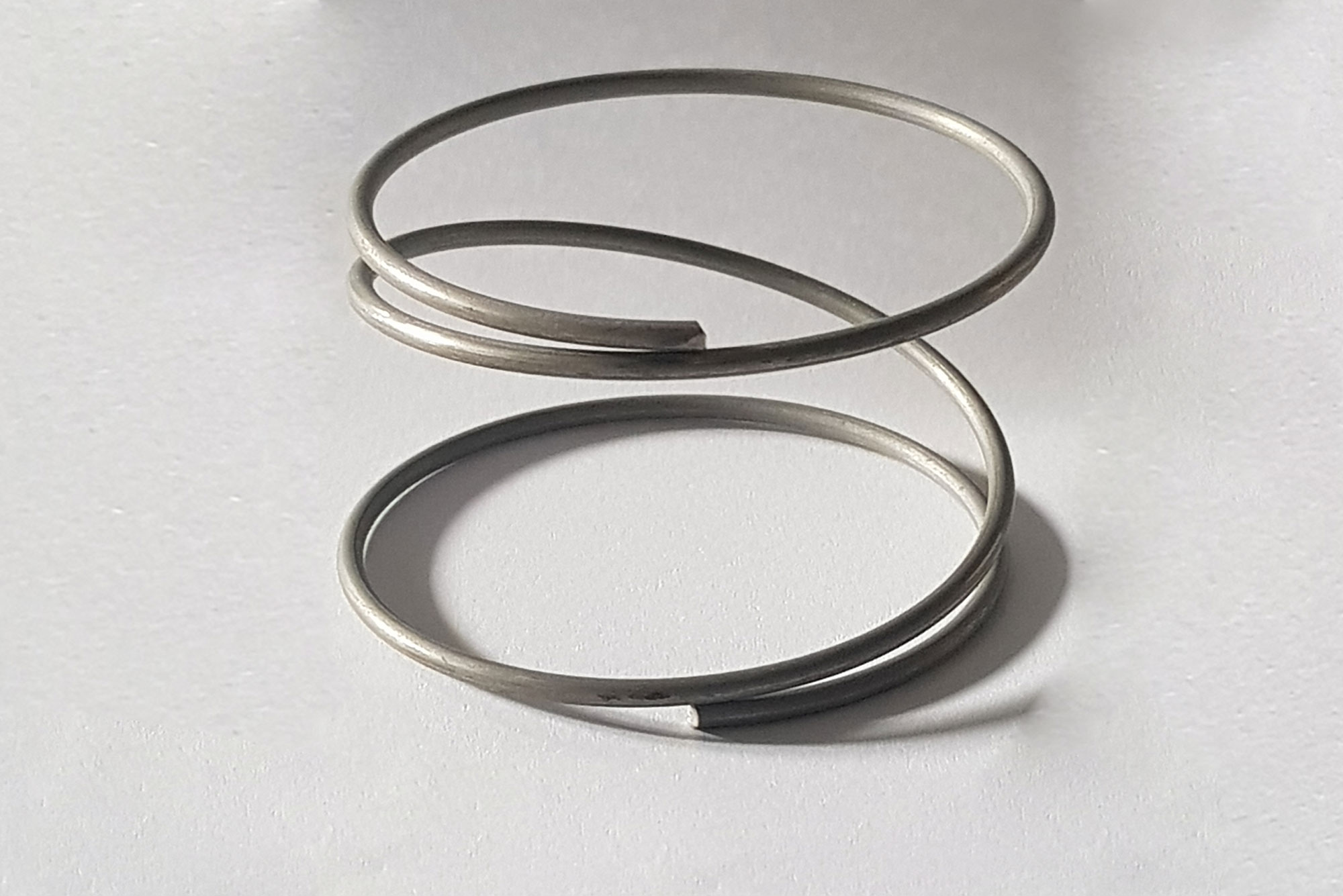
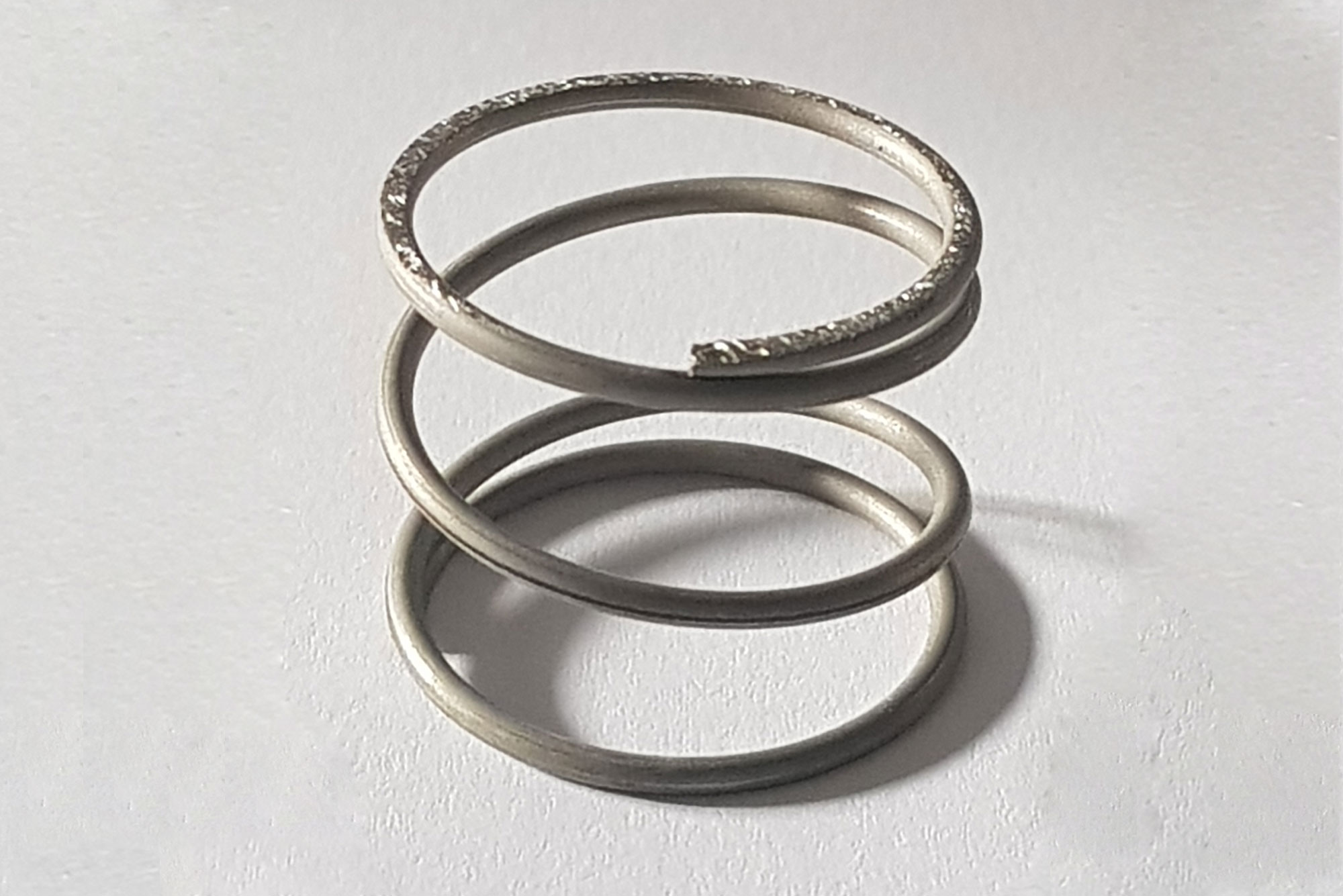
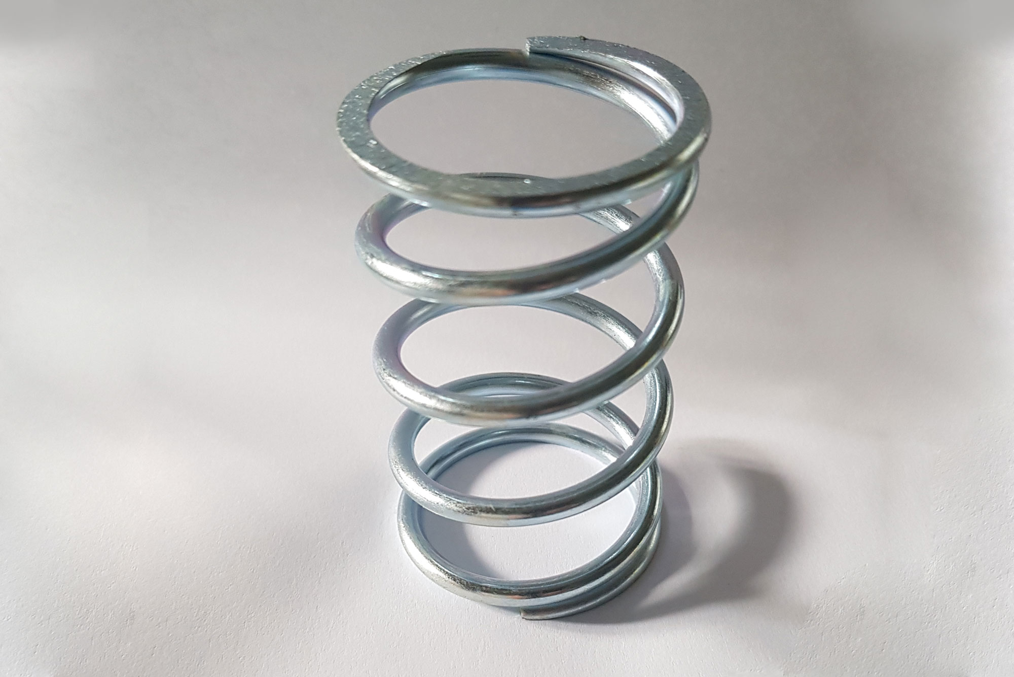
The following are a few sample images
Closed and square ends (right-hand wound)
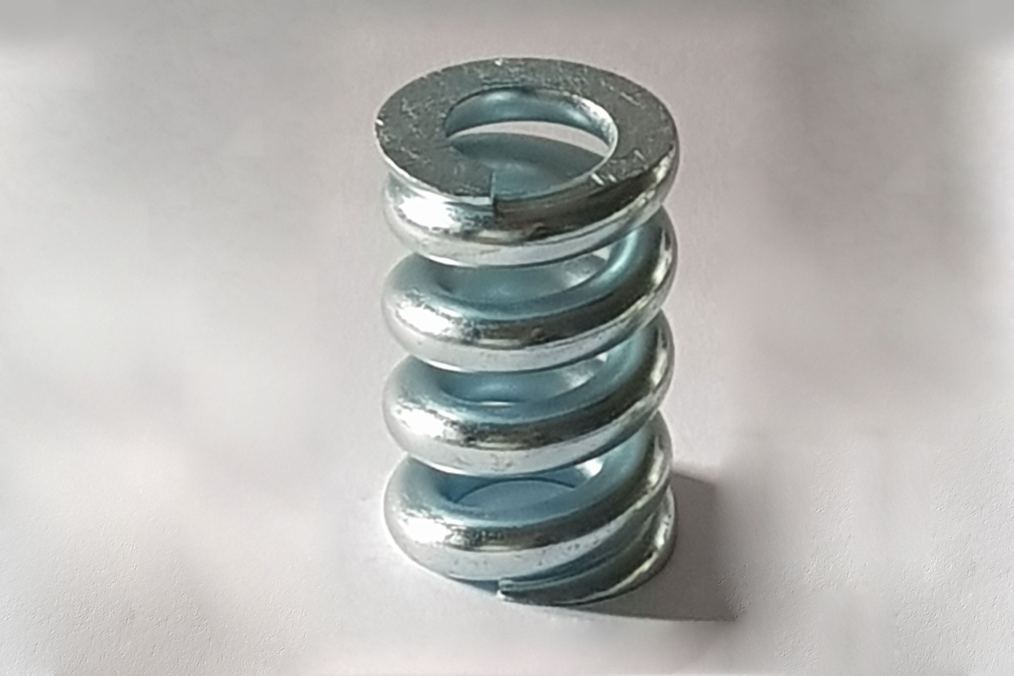
Closed and ground ends (left-hand wound)
The number of total turns (counting the complete windings)
If you don’t know the number of coils you can tell us the pitch
(distance between the centers of two adjacent active coils)
Or the light (distance between two adjacent turns)
The free length (the length of the spring is not subject to any load)
The working lengths with the relative required loads (normally 2, the preload and the maximum elongation)
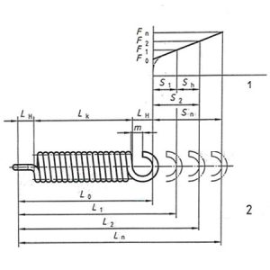
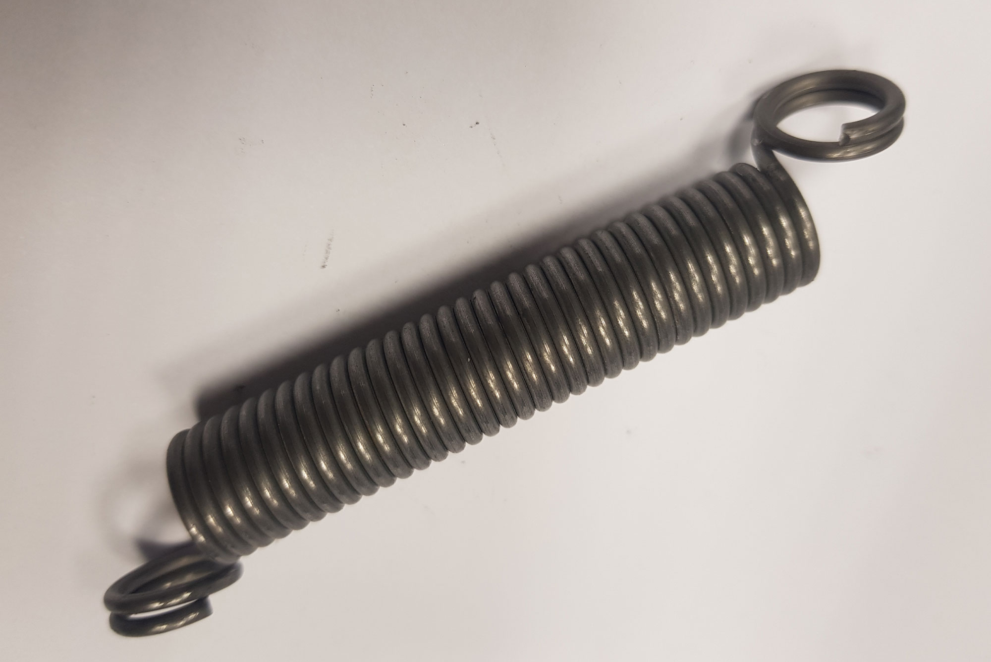
With regard to extension springs you have to indicate :
– Free Length L0 ( measured inside the eyelets)
– Outside diameter
– Length of the body Lk or total of coils
– Eye Lenght LH
– Working length L1 and L2 with the required loads
– The maximum allowable length of the spring , under the eligible load Ln
It is also necessary to indicate the type of hooks at the edges based on assembly and tension requirements
as well as their position (oriented in the same position or at 90 degrees for example) and the
opening of the hooks themselves. Below are some examples:
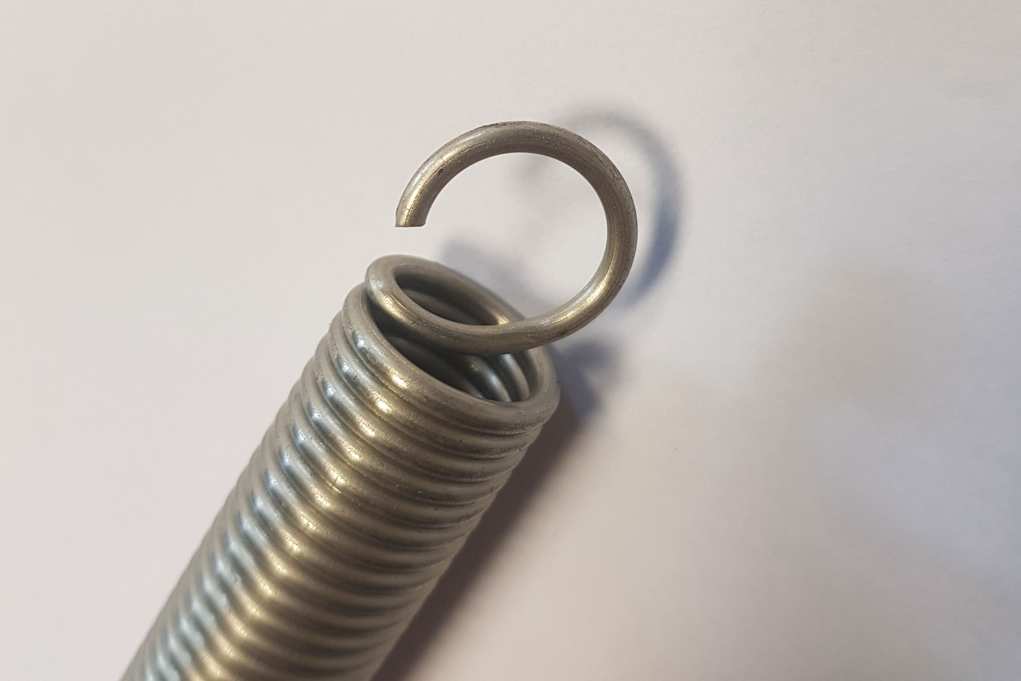
English hook / Cross over center hook
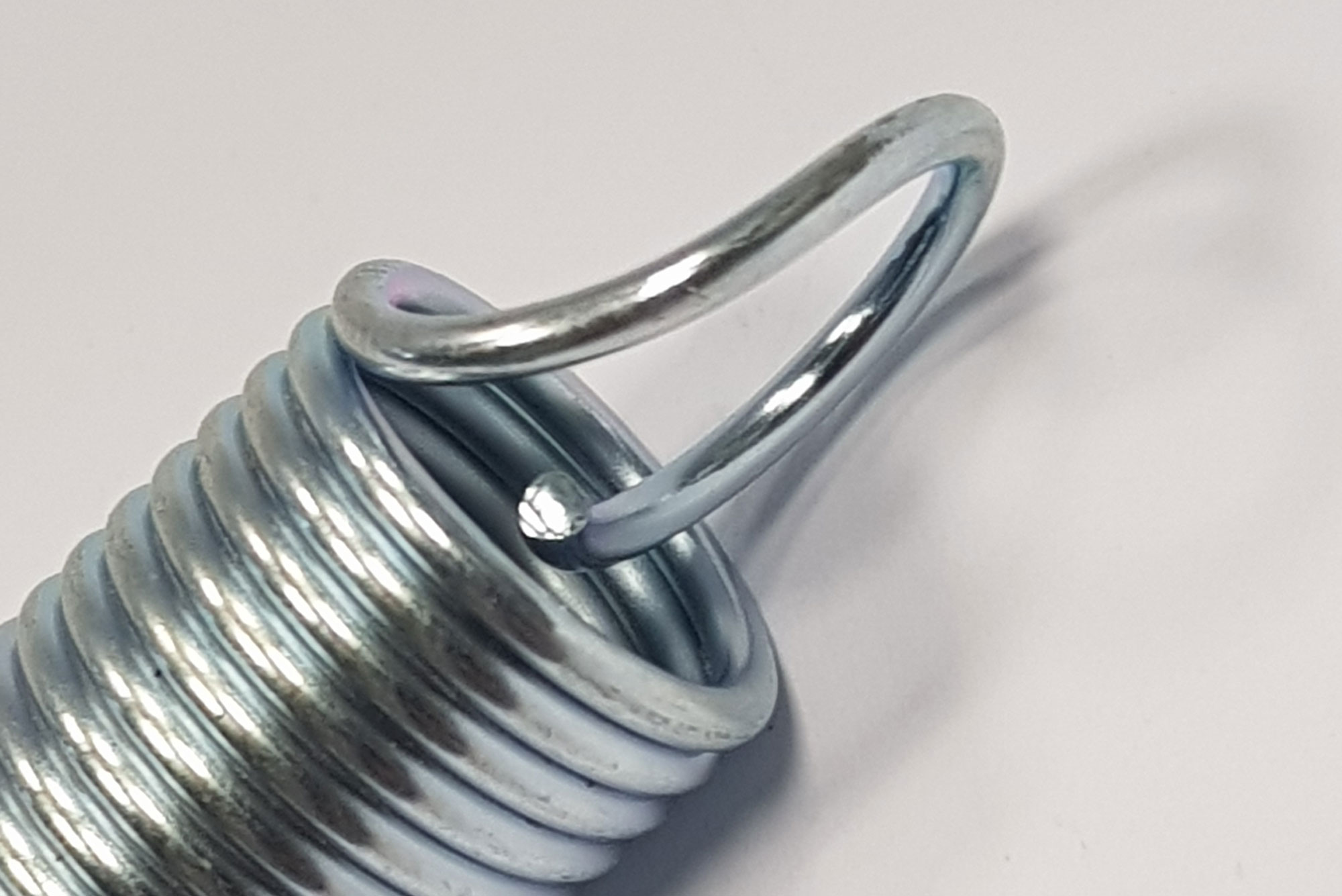
German hook / machine hook

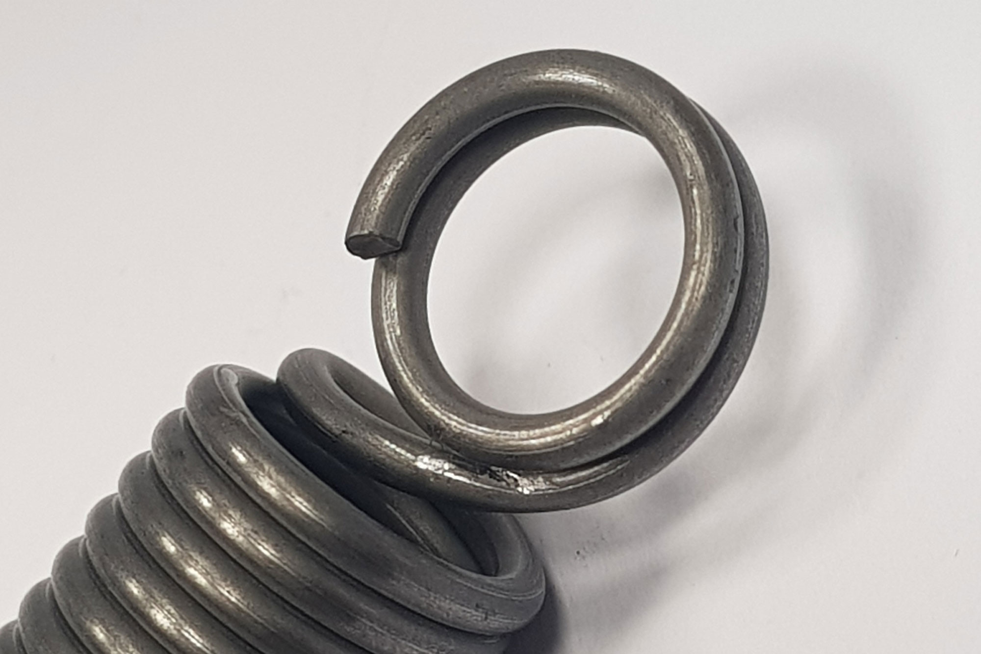
Side hooks
Double english hook
Double side hook

Extended hook
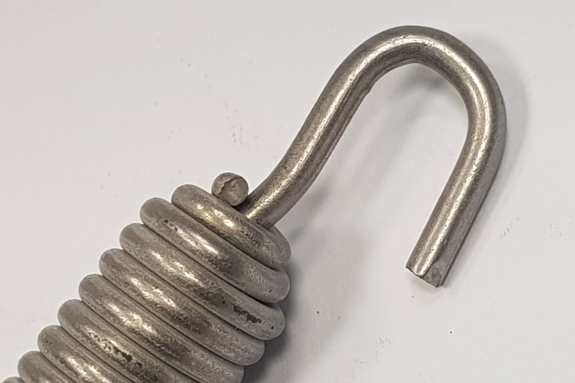
Swivel hook
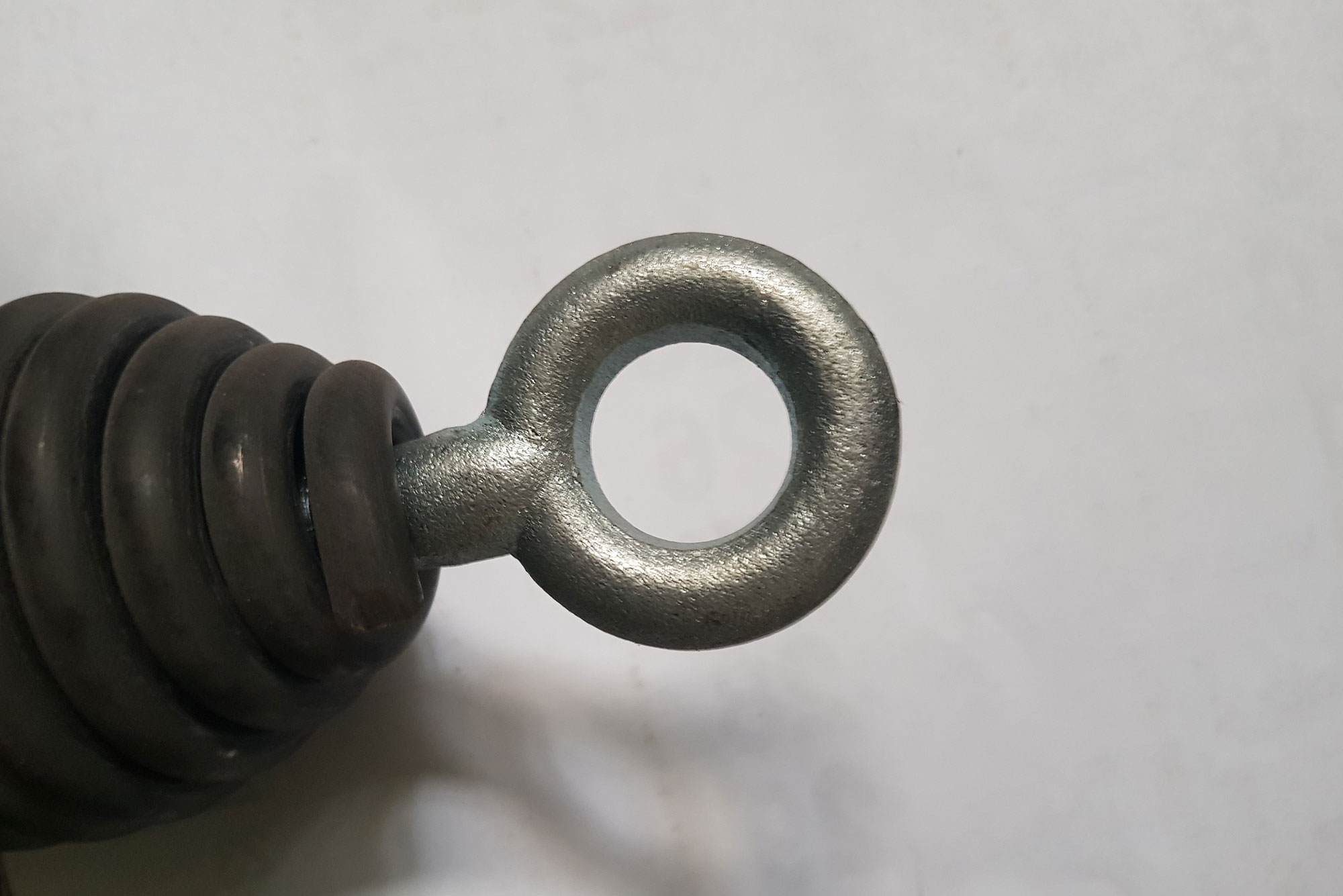
Coned end with swivel hook
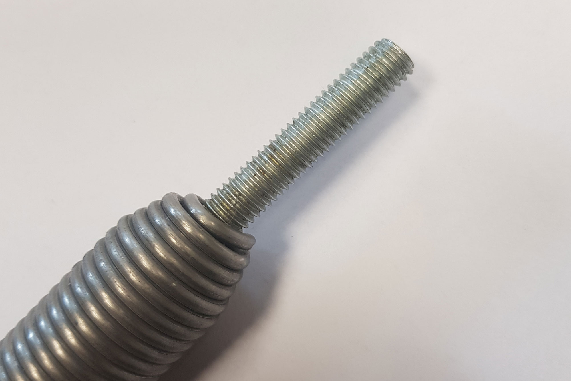
Coned end with swivel bolt
As concerns Torsion springs, shaped components in wire and strip form/metal stampings we absolutely
need a sample or a drawing, possibly including a 3d representation of the component
